Wednesday, 27 April 2011

Learning Processing: Chapter 5.4-5.5

CHAPTER 5.4 - LOGICAL OPERATORS:
So, what on earth are "logical operators", wikipedia defines them as "A symbol or word used to connect to or more sentences in a grammatically valid way".
Not that I really understand that, for things I don't understand, I find it massively helpful to apply the mathematical paradigm of abstraction, instead of comprehending the (I'm pretty sure it's used in other fields as well, but this is where I first came upon it, just a warning to the pedants!).

So what properties do logical operators have, there are 3:

NOT - !
AND - &&
OR - ||

NOT is used to invert a boolean expression, so if we asked the question "Is the sky blue", NOT would return "false" thus having inverted "true"

AND is used to compare two boolean expressions and only return "true" if both of the 2 expressions are satisfied. For example if we were to ask the question "is the sky blue AND is the sea blue" processing would return "true" if we asked "is the sky blue AND the sea orange" processing would return "false", although one of the expressions is true, the other is false, AND only returns true when both expressions are true.

OR is like AND, however only one of the expressions has to be true to for it to return 'true', for example "is the sky blue OR is the sea orange", this returns 'true' because the first expression is true, even though the second is false.

Looking at what I've just written, that is an incredibly lengthy explanation for such simple concepts, I blame this on wikipedias overly wordy explanation of a 'logical operator' and it being quite late... now with the explanations dispensed, time to document the chapter.


In 5.4 we write a simple program to change a rectangles colour when the mouse is over it. I expanded on this code a bit and implemented a multiple rollover, when the mouse is not on the rectangle, the background is black and the rectangle white. When the mouse is on the rectangle, the background is white and the rectangle black. Hopefully the code is commented well enough for most people to understand!

 /* logical operators in use in a simple sketch, && is AND
|| is OR */

void setup() {
size(200,200); //200x200 canvas
smooth(); //set anti-aliasing
}

void draw() {
background(255); //set backgroudn white
if (mouseX > width/2 && mouseY > width/2) { //if mouse X coord is on the right AND the mouse Y coord is on the bottom half of the canvas
fill(0); //fill rect with black
rect(width/2,height/2,width/2,height/2); //draw rect at bottom right
}
else if (mouseX < width/2 || mouseY < height/2) { //else if the mouse X coord is less than half of the width OR the mouse Y coord is above the middle of the canvas
background(0); //fill background with black
fill(255); //fill rectangle with white
rect(width/2,height/2,width/2,height/2); //draw rect at bottom right
}
}


In 5.5 we learn to implement 'multiple rollovers' Shiffman has provided some pseudocode of his next example, however I decided to implement it myself before going ahead and reading his example, as usual my code is cruder, less well written and much harder to mod, but I'm proud of it, it accomplishes the same thing as Shiffman's code.

MY CODE:

int w = 200; //width of canvas
int h = 200; //height of canvas
int c1 = 255; //colour1 = white
int c2 = 255; //colour2 = white
int c3 = 255; //colour3 = white
int c4 =255; //colour4 = white

void setup() {
size (w,h); //set canvas size
smooth(); //anti-aliasing
rectMode(CORNER);
}

void draw() {
if (mouseX < width/2 && mouseY < height/2) {
c1 = 0;
c2 = 255;
c3 = 255;
c4 = 255;

} else if (mouseX < width/2 && mouseY > height/2){
c1 = 255;
c2 = 255;
c3 = 0;
c4 = 255;

} else if (mouseX > width/2 && mouseY < height/2) {
c1 = 255;
c2 = 0;
c3 = 255;
c4 = 255;

} else if (mouseX > width/2 && mouseY > height/2) {
c1 = 255;
c2 = 255;
c3 = 255;
c4 = 0;
}

background(255); //set white background
fill(c1);
rect(0,0,width/2,height/2);
fill(c2);
rect(width/2,0,width/2,height/2);
fill(c3);
rect(0,height/2,width/2,height/2);
fill(c4);
rect(width/2,height/2,width/2,height/2);

println("X = " + mouseX + " Y = " + mouseY);
}


 // Learning Processing
// Daniel Shiffman
// http://www.learningprocessing.com

// Example 5-3: Rollovers
void setup() {
size(200,200);
}

void draw() {
background(255);
stroke(0);
line(100,0,100,200);
line(0,100,200,100);

// Fill a black color
noStroke();
fill(0);

// Depending on the mouse location, a different rectangle is displayed.
if (mouseX < 100 && mouseY < 100) {
rect(0,0,100,100);
} else if (mouseX > 100 && mouseY < 100) {
rect(100,0,100,100);
} else if (mouseX < 100 && mouseY > 100) {
rect(0,100,100,100);
} else if (mouseX > 100 && mouseY > 100) {
rect(100,100,100,100);
}
}


Right, I think that's it for tonight...

Monday, 25 April 2011

Learning Processing: Chapter 5.1 - 5.3

CHAPTER 5: CONDITIONALS:
So today I taught myself to use conditionals (haven't finished the chapter yet!). Boolean expressions are the foundation of conditionals, a boolean expression is a true/false question, these are the only types of questions computers can answer. An example of a boolean expression:
"15 > 20 false"
In processing there are 3 types of conditionals:

- if statements
e.g. "If x>y do something"

- else statements
e.g. "If x>y (do something), else (do this instead)"

- else if statements
e.g. "If x>y (do something), else if (do this instead), else (quit)"

You can only ever have 1 else and 1 if in a sketch,

Ex 5.1:
(check this out on the open processing website, it needs to be run multiple times to give different background colours and prints stuff in the command line, maybe just DL the code and paste it in processing and run it)


Ex 5.2 gave me a bit of trouble, I couldn't figure out what was wrong in the code on the 2nd problem. I didn't spot two if statements were used vs. 1 if and 1 else (which is what the second column of code uses).

Shiffman's website is pretty great, It's really handy to be able to check out whether you are wrong or right and you can just paste the code if you can't be bothered to write it out (which I don't usually do, I usually think about whats happening when I type it in, tonight I couldn't be bothered though!)

5.3 CONDITIONALS IN A SKETCH

The first part of chapter 5.3 gives you some pseudo code, I wanted to test my coding skills so before turning the page I implemented the steps into code to see how my code compared to Shiffman's.


My Code:
 //set values and types of variable of RGB.

float r = mouseX;
float g = 100;
float b = 150;

// set window size and enable anti-aliasing
void setup() {
size(200,200);
smooth();
}

//start loop
void draw() {

if (r > 255) { //if 'r' is bigger than 255 set it to 255 (i.e. limit it)
r = 255;
}
else if(r < 0) { //if 'r' is smaller than 0 set it to 0 (limit it)
r = 0;
}
else {
println("r = " + r); //print line to debug to make sure 0<r<255
}


if (mouseX <= 100) { //if mouseX is on the left increase 'r' value by 5
r = r + 5;
}
else if (mouseX > 100) { // if mouseX is on the right decrease 'r' value by 5
r = r - 5;
}
background(r,g,b);
}


// Learning Processing
// Daniel Shiffman
// http://www.learningprocessing.com

// Example 5-1: Conditionals

// Variables
float r = 150;
float g = 0;
float b = 0;

void setup() {
size(200,200);
}

void draw() {
// Draw stuff
background(r,g,b);
stroke(255);
line(width/2,0,width/2,height);


// If the mouse is on the right side of the screen is equivalent to
// "if mouseX is greater than width divided by 2."
if(mouseX > width/2) {
r = r + 1;
} else {
r = r - 1;
}

// If r is greater than 255, set it back to 255.
// If r is less than 0, set it back to 0.
if (r > 255) {
r = 255;
} else if (r < 0) {
r = 0;
}
}


Arghh! And then after all that we learn there is a function named "constrain()" which does this all for you e.g. r = constrain(r,0,255);
That would have been far easier, but it's nice to know I understand the concept of how to implement constraints without a specialised function.

Example 5.2 improves upon this last sketch by changing r,g and b. It also makes use of the constrain() function.


// Learning Processing
// Daniel Shiffman
// http://www.learningprocessing.com

// Example 5-2: More conditionals

// Three variables for the background color.
float r = 0;
float b = 0;
float g = 0;

void setup() {
size(200,200);
}

void draw() {
// Color the background and draw lines to divide the window in quadrants.
background(r,g,b);
stroke(0);
line(width/2,0,width/2,height);
line(0,height/2,width,height/2);

// If the mouse is on the right hand side of the window, increase red.
// Otherwise, it is on the left hand side and decrease red.
if (mouseX > width/2) {
r = r + 1;
} else {
r = r - 1;
}

// If the mouse is on the bottom of the window, increase blue.
// Otherwise, it is on the top and decrease blue.
if (mouseY > height/2) {
b = b + 1;
} else {
b = b - 1;
}

// If the mouse is pressed (using the system variable mousePressed)
if (mousePressed) {
g = g + 1;
} else {
g = g - 1;
}

// Constrain all color values to between 0 and 255.
r = constrain(r,0,255);
g = constrain(g,0,255);
b = constrain(b,0,255);
}

In 5.4 I'll learn about Logical operator (AND, OR, NOT) which looks quite interesting and should hopefully be transferable to logic circuits when I get to them in MAKE: Electronics. This was quite a quite a long chapter so far, it's been hard but rewarding. I'm glad I've tried to implement the examples myself before looking at the code, it makes sure I understand the principles even if it is tough going!

MAKE: Electronics: Experiment 16: 555 timer


INTRODUCTION TO THE 555 TIMER:


So, we finally get to play with some ICs now! I feel I have quite a good understanding of the basic components now, so in the coming weeks I shall have a go making some circuits up using transistors etc.

The 555 timer is perhaps the most ubiquitous IC on the planet, it is estimated that 1 billion per year are still produced, it has 3 modes:


- Monostable mode - This means that when the IC is triggered it produces one pulse, it can be used to trigger other ICs. A square waveform pulse is produced.


- Astable mode - This means that when triggered the IC acts as an oscillator, it is not stable, hence the astable name. This
is useful for flashing LEDs, producing tones on speakers etc. A square waveform is produced.


- Bistable mode - When triggered the IC acts as a flip flop, this is useful to remove the bounce (http://www.elexp.com/t_bounc.htm) from a switch. I don't really know much about flips flops, but I guess later on in the book when logic will have been covered I'll have a greater understanding of the concept.


Pinouts:
(refer to the top diagram)
1 - (GND) Connected to GROUND
2 - (TRIG) Trigger, pull low when you want to trigger the chip (1/3 of Vs)
3 - (OUT) The pulses are delivered here (+V)
4 - (RESET) Pull low when you want to reset the chip
5 - (CTRL) Control, access to the internal voltage divider to change the threshold voltage (default > 2/3 Vs) which pulls pin 3 low (0V)
6 - (THR) Threshold, when pulled high (2/3 Vs) it sets pin 3 to 0V
7 - (DIS) Discharge, when a pulse is initiated, the capacitor attached to this pin discharges through it to ground, this is the timing capacitor, hence the larger the value, the longer it takes to discharge and the longer the pulse
8 - (Vcc) Positive supply voltage, from 3 - 15V

The Circuit : Monostable mode
This experiment uses the 555 timer in 'monostable' mode, when we trigger the chip, it will emit a pulse of a length determined by the capacitor attached to pin 6, the larger the capacitance, the longer the length of the pulse.

The circuit is wired up so when a button is pressed, it pulls pin 2 low, triggering the IC, a pulse is delivered on pin 3 thus powering the LED in the circuit. A potentiometer is connected in between the switch (connected to the trigger) and ground, by varying this pot, the pin is pulled to differing voltages, only if the pin is pulled below 1/3 of the supply voltage will the IC be triggered.

I plan on playing a bit with this chip and documenting my experiences further, I'm getting quite a good idea of how to use it.

Friday, 22 April 2011

MAKE: Electronics: Experiment 15 (Burglar Alarm)

EXPERIMENT 15: INTRUSION ALARM (REVISITED):


(this video is showing how the relay is wired up, once the sensor circuit is broken (open) the relay energises, when the sensor circuit is closed, the relay stays energised)


Part 1: Stripboard Layout:
This experiment calls for a protoboard in the same layout of a breadboard, which does seem a great way to introduce beginners to transferring projects from solderless breadboard to permanent perfboard. However I found this nigh on impossible to find in the UK. I settled using a perfboard and arranging the layout in a somewhat similar manner to a breadboard.
The picture shows the top side and under side of the board, I have mirrored the photograph so the top right of the up side = the top right of the under side, basically, you can overlay the pictures over each other as they correspond (I'm not really sure how to say this more clearly!)

From MAKE Electronics: Experiment 15: Burglar Alarm

At the top of the board is the alarm circuit created back in experiment 11. At the bottom is a circuit that when triggered by an opening in the sensor circuit (i.e. opening a door) turns power on to the alarm circuit. If the sensor circuit is then closed again (door closed) power is still supplied to the alarm so it does not turn off. This is explained exceptionally well in the book however I think I only truly appreciated how the circuit worked when making my own (far less elegant) arrangement on a breadboard to see how it all worked from the schematic diagram.

I soldered everything on the stripboard first, then I took a dremel to it with a cutting wheel and trimmed it down and then sanded the sides, it fits in just between the slots in the project box so I don't have to screw it down (very convenient!).

Part 2: Project Box
The point of this experiment is to show how one goes from a fairly minimalist circuit on the breadboard to a fully-fledged project. This requires casing to maintain the longevity of the project and also somewhere to mount a user interface. The UI for this project is fairly simple, it consists of:
(i) An Arming button - arms the alarm (and lights green LED to indicate the alarm is armed)
(ii) A Test button - (un-armed) lights up LED when sensor circuit is close, (armed) tests alarm circuit/speaker
I added some banana plugs to my magnetic sensor, I currently don't have anywhere to put it, Platt says later in the book that I'll learn how to integrate an 'away from home' feature and add a keypad to it (Hopefully I can figure out how to use a matrix keypad instead of a common pin type keypad) So I might get round to using it pending on how well it turns out. When activated the alarm isn't exactly loud so I will build an amplifier circuit at some point (I tried driving it with an old amp and it goes fairly loud for its size, it can certainly be ear piercing)

Thursday, 21 April 2011

Why I hate textbooks

Just a quick reflection for now before I post about my new burglar alarm (courtesy of experiment 15 in MAKE: Electronics). One thing that I continually keep on doing is buying textbooks, putting them in my cupboard to read when the time comes that I need to seek help - however, I never do end up looking at them, I have the internet, with interactive information; videos, exercises all in one place, If I don't understand a term I'll look it up on wikipedia. Why do I continue to irrationally buy these textbooks when I know I have a very low chance of ever reading them? I like to think it's because once I've spent that amount of cash on a book, it will be presented exactly how I would like it to be, easily digestible, easily understood. It's almost as if when I buy it I expect to know the contents of it once owning it, sadly not the truth. I'm becoming more and more reliant on internet resources nowadays, Kahn Academy is playing a big role in my education now, well sorted, comprehensive videos on what I need to learn for college and more all in an easily accessible place, just a button click a way. I'm going to try and refrain from buying more textbooks, spending time looking for them and reading reviews, I'm going to try and find more online resources. I like that they're free (the majority) therefore I can't "own" it per-say which results in me putting time and effort in learning the content vs. "owning" it and assuming I can learn it when the time comes around.

Sunday, 17 April 2011

Learning Processing: Chapter 4

CHAPTER 4: Variables

Chapter 4 is the start of 'Lesson 2' focussing on the rest of the basics of programming: variables, conditionals and loops.

A variable is a pointer to a location in the computers memory where a value is stored. This value can vary hence the name. The chapter introduces the different types of variables; int, float, boolean, char, byte, short, long and double. Each should be used in a different circumstance depending on the need, the book explains where to use each one clearly and concisely. Variables can be named, and addressed in a sketch. for example mouseX is an integer storing the mouses X-coordinate - this is a system-wide variable, one already established in processing, these are mainly commonly used variables (e.g. frameCount) and so have been built into the language.

The exercise for using system variables gets you to create a little picture out of basic geometry that will scale itself accordingly when you change the size of the window. I thought that the large square was itself a square and not the bounds of the size therefore my code is somewhat different to the code posted on Shiffmans website as I shall ellaborate on.


Shiffman's Code:


random()
is another function you learn how to use in this chapter. It focusses on using it in variables to create movement (e.g. Zoog the alien moving from side to side). The syntax is as follows random(low value bound,high value bound) - It's pretty easy to start implementing random values into your sketches after learning the basics.

Thursday, 14 April 2011

MAKE: Electronics: Experiment 14

EXPERIMENT 14: A PULSING GLOW:
This project takes your new found knowledge of soldering, breadboarding and PUTs to make a pulsing LED mounted on stripboard. I found this fairly easy, but it was a good practice of translating schematic to stripboard, the book does have a diagram of how the components should be arranged; but you can try and convert it yourself first before doing this - it is good practice!

The way the circuit works is that the capacitor connected to the anode charges, when it reaches a voltage high enough to pass through the gate the capacitor discharges passing current to the LED, the capacitor discharges resulting in the LED fading from bright to dim. However unlike the last LED oscillating circuit in the book there is a capacitor attached to the LED provide it with current, so it doesn't flash on and off, as instead of turning off the LED is provided with enough current to be lit dimly this creates a 'pulsing glow' as Platt puts it.


From MAKE Electronics: Videos

Wednesday, 13 April 2011

MAKE: Electronics: Experiment 13

EXPERIMENT 13: BROIL AND LED:

This experiment demonstrates how heat affects components - in particular, the LED. One heats the LED with a soldering iron for a while with a copper aligator clip (which diverts heat from the LED, thus preventing it from damage). After you remove it and just use the soldering iron on its own, it's luminosity slowly decreases in intensity for a period of time before it burns out due to excessive heat.
OK, I have a little confession to make, I failed this experiment, the LED only got slightly dim after 5 minutes of my soldering iron at 450°C so I gave up!

The stop watch indicates how long the iron had been applied to the LED and the iron station shows the temperature the iron was at.

Learning Processing: Chapter 3

Chapter 3: 'Interaction'

Chapter 3 covers the 'flow' of a program; what setup() and draw() do and how to use them, mouse interaction, dynamic sketches and finally handling events (mouse clicks and key presses).

I've learnt that setup() is run only once when the sketch is run, it sets the 'initialization code' as Shiffman puts it. After setup(), draw() is run, this runs, then loops back to the start of the code:

void setup() {
//setup code
}

void draw() {
//code which loops
}

The { } host a 'block of code' allowing one to manage code as an individual part of a program.

MOUSE FUNCTIONS:
mouseX - the current mouse x-coordinate
mouseY - the current mouse y-coordinate
pmouseX - the mouse x-coordinate in the previous run through draw()
pmouseY - the mouse y-coordinate in the previous run through draw()
void mousePressed() - function that runs code when a mouse button is pressed
void keyPressed() - function that runs code when a key on the keyboard is pressed


I feel I have a good understanding of all the above, I am starting to realise how one goes about programming and how hard it will be in future implementing features, it shall definitely improve my logic, something I have been looking forward to doing, it's not very often we get stretched in school!

This chapter completes 'Lesson 1' which covers the beginning of learning to program in processing. The end of lesson project is to create a dynamic sketch by interaction of the mouse and a static drawing. I have drawn a few things and added dynamics to them, currently I can't figure out how to export programs that actually display in webpages out, once I figure that out, they will be posted here.

Learning Processing: Chapter 2

Chapter 2 focusses on the topic of 'Processing':
- How to get the IDE
- Introducing the 'sketchbook'
- Interface
- The processing reference

Essentially it is quite a dull chapter if you have already used the Processing IDE before but to those new to it, it will prove a nice introduction as to how to use the IDE and the reference.

One problem I have found is with 'publishing' my programs, when I export them, and I have a folder containing the code and index.html, when I open index.html I don't see my program, the layout is how it should be but just a box where my program should display. I'm not sure what is causing this problem so I may have a browse on the processing forums to try and find a remedy to this problem!

Monday, 11 April 2011

Learning Processing: Chapter 1


I've picked up another book to delve into, I've always wanted to learn to program, 'Processing' seemed the logical choice Arduino (the programming language) is based on processing so I shall get a better understanding of syntax and how programs are written including the logic behind how they are structured (I've always been fascinated by this), thus giving me a step up when I go back to microcontrollers (after finishing this & Make: Electronics).

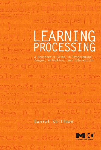
The book is called "Learning Processing" by Daniel Shiffman

A few things drew me to this book, I like how it really takes you from not knowing a thing about programming, to a decent foundation. I think it is very important to learn the theory so when it comes to learning different languages you still have a thorough understanding of the paradigm but you only have to pick up the new aspects of the language.

Processing is a language based on visual interaction vs text-based interaction. A program is written with text, displayed using visual then can be interacted with via mouse clicks (amongst other devices). Text-based languages operate by being written in text, producing text and then being interacted with by more text. Enough rambling, onto the first chapter...

CHAPTER 1: Pixels
This chapter focuses on 'Pixels', it describes how to draw some basic euclidean shapes (e.g. lines, circles and triangles etc), colour theory (grayscale, RGB, transparency) - that's about it. The book introduces different exercises to have a bash at to make sure you understand and can implement the theory - I personally find this the strong point on the book so far (Yes, I am only on chapter 2 at the moment!)

I've learnt that the grid the computer draws is different to the "Cartesian coordinate system" (The one you use in mathematics at school). The x-axis is drawn from left to right (lower -> higher value. This is the same as in the 'normal' graph system) however the y-axis is drawn from top to bottom, as you go down the y-value increases (not negatively).
I also have learnt how to draw - Rectangles, ellipses, triangles, lines and points, I know how to change line thickness, set the outline to be a different colour, set the inside to be a different colour etc. I don't quite understand how the colour mixing RGB system works yet, the mixing works like mixing lights; I've never really understood how that works thus I will check out a few tuts later on this week on the subject.

At the end of the chapter you have to draw your own 'character' in processing, mine is fairly appalling compared to Shiffman's but it is original and I feel proud to have accomplished something.

I tried to upload the code to openprocessing but it isn't displaying - not too sure why..
Here is the code.


Thursday, 7 April 2011

MAKE Electronics: Experiment 12

Joining 2 wires together:

I have already soldered quite a bit prior to this so it was more a chance to hone my skills than learning anything new, however I had never soldered low gauge wire, so this was a new experience for me, larger diameters do need more power and my Weller could just about handle the wire in the power chord, I'm not sure how I'd feel about using a 'soldering gun' they look rather unwieldy, I do have a low quality Weller hobby one in the garage which I might have a bash using at some point in the future.

The first 2 solder joints, the first joint joined the wires across each other in an 'x' shape, this went well. The second joint joined the wires parallel to each other, again, this proved to be successful, I heat shrinked the wires and was fairly happy with my hand work.

Next I chopped up a long power chord and made it much shorter, I joined each individual wire and heat shrinked all 3 individually, then used some electrical tape on the outside of this as I didn't have a larger enough diameter of heat shrink to use for this purpose. I tested this cable out on my soldering iron, it worked flawlessly, I was somewhat hesitant as I thought I might end up tripping the breakers with a short circuit - this did not happen fortunately!