Showing posts with label MAKE: Electronics. Show all posts

Friday, 6 May 2011

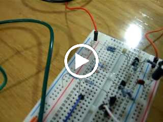
MAKE Electronics: Experiment 17: Emitting a tone (555)

PART 1:
This experiment sets the 555 up in astable mode (check out the previous post for an explanation). The 555 will emit pulses at a certain frequency which will drive the speaker. Changing the frequency of the pulses will then in turn change the frequency of the speaker's tone. To change the pulse frequency or rate, we adjust the external capacitor connected to pin 6, the threshold pin. (or the resistor between 6 & 7)
From MAKE: Electronics: Experiment 17 (555 in astable mode)

Here's the circuit, lets have a look at the schematic of the 555 in astable mode again:

So the THRESHOLD is connected to the TRIGGER, when the cap, C, is charged past 2/3 of the Vsupply the threshold is passed and the capacitor discharges through R2 into pin 7 (DISCHARGE) and a pulse is emitted from OUT. Once the cap has discharged and the IC is no longer triggered, the cap starts charging again, when it reaches 2/3 Vsupply it repeats the process, this results in a series of pulses, this is called a square wave oscillator, because it's producing a a series of square wave pulses. This is great for generating tones on speakers, flashing LEDs (albeit highly overkill!) etc.

PART 2:
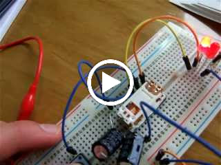
Now we chain 2 chips together, both in astable mode, this produces a warbling tone.
The 555 on the left (IC2) is working in the same way as in part 1, however this time, a second 555 (IC1) is chained to the chip with it's output attached to pin 5 of the tone generator 555 (IC2). When IC1 produces a pulse it increases the voltage at pin 5 (2/3 Vsupply results in the chip emitting a pulse) so when IC1 emits a pulse and triggers the second chip to generate a pulse the capacitor attached to pin 5 of IC2 is less charged than it would have been if IC1 wasn't chained to IC2, this results in a higher pitch, because IC1 is oscillating far slower than IC2, IC2 isn't always triggered by a pulse from IC1 meaning it operates in its normal mode and produces a lower frequency tone.

This results in a warbling sound to be produced as some of the time IC2 is producing high frequency square waves (when IC1 is emitting a pulse) and some of the time IC2 is producing lower frequency square waves (when IC1 is not emitting a pulse)


(the video shows the circuit the other way round, sorry about that!)

There is a hell of a lot of info in this experiment so I think I'll spend some time playing around with the 555 trying to figure out how to get it to emit different pulses, an oscilloscope would be great to have around for this experiment!

Monday, 25 April 2011

MAKE: Electronics: Experiment 16: 555 timer


INTRODUCTION TO THE 555 TIMER:


So, we finally get to play with some ICs now! I feel I have quite a good understanding of the basic components now, so in the coming weeks I shall have a go making some circuits up using transistors etc.

The 555 timer is perhaps the most ubiquitous IC on the planet, it is estimated that 1 billion per year are still produced, it has 3 modes:


- Monostable mode - This means that when the IC is triggered it produces one pulse, it can be used to trigger other ICs. A square waveform pulse is produced.


- Astable mode - This means that when triggered the IC acts as an oscillator, it is not stable, hence the astable name. This
is useful for flashing LEDs, producing tones on speakers etc. A square waveform is produced.


- Bistable mode - When triggered the IC acts as a flip flop, this is useful to remove the bounce (http://www.elexp.com/t_bounc.htm) from a switch. I don't really know much about flips flops, but I guess later on in the book when logic will have been covered I'll have a greater understanding of the concept.


Pinouts:
(refer to the top diagram)
1 - (GND) Connected to GROUND
2 - (TRIG) Trigger, pull low when you want to trigger the chip (1/3 of Vs)
3 - (OUT) The pulses are delivered here (+V)
4 - (RESET) Pull low when you want to reset the chip
5 - (CTRL) Control, access to the internal voltage divider to change the threshold voltage (default > 2/3 Vs) which pulls pin 3 low (0V)
6 - (THR) Threshold, when pulled high (2/3 Vs) it sets pin 3 to 0V
7 - (DIS) Discharge, when a pulse is initiated, the capacitor attached to this pin discharges through it to ground, this is the timing capacitor, hence the larger the value, the longer it takes to discharge and the longer the pulse
8 - (Vcc) Positive supply voltage, from 3 - 15V

The Circuit : Monostable mode
This experiment uses the 555 timer in 'monostable' mode, when we trigger the chip, it will emit a pulse of a length determined by the capacitor attached to pin 6, the larger the capacitance, the longer the length of the pulse.

The circuit is wired up so when a button is pressed, it pulls pin 2 low, triggering the IC, a pulse is delivered on pin 3 thus powering the LED in the circuit. A potentiometer is connected in between the switch (connected to the trigger) and ground, by varying this pot, the pin is pulled to differing voltages, only if the pin is pulled below 1/3 of the supply voltage will the IC be triggered.

I plan on playing a bit with this chip and documenting my experiences further, I'm getting quite a good idea of how to use it.

Friday, 22 April 2011

MAKE: Electronics: Experiment 15 (Burglar Alarm)

EXPERIMENT 15: INTRUSION ALARM (REVISITED):


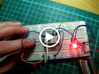
(this video is showing how the relay is wired up, once the sensor circuit is broken (open) the relay energises, when the sensor circuit is closed, the relay stays energised)


Part 1: Stripboard Layout:
This experiment calls for a protoboard in the same layout of a breadboard, which does seem a great way to introduce beginners to transferring projects from solderless breadboard to permanent perfboard. However I found this nigh on impossible to find in the UK. I settled using a perfboard and arranging the layout in a somewhat similar manner to a breadboard.
The picture shows the top side and under side of the board, I have mirrored the photograph so the top right of the up side = the top right of the under side, basically, you can overlay the pictures over each other as they correspond (I'm not really sure how to say this more clearly!)

From MAKE Electronics: Experiment 15: Burglar Alarm

At the top of the board is the alarm circuit created back in experiment 11. At the bottom is a circuit that when triggered by an opening in the sensor circuit (i.e. opening a door) turns power on to the alarm circuit. If the sensor circuit is then closed again (door closed) power is still supplied to the alarm so it does not turn off. This is explained exceptionally well in the book however I think I only truly appreciated how the circuit worked when making my own (far less elegant) arrangement on a breadboard to see how it all worked from the schematic diagram.

I soldered everything on the stripboard first, then I took a dremel to it with a cutting wheel and trimmed it down and then sanded the sides, it fits in just between the slots in the project box so I don't have to screw it down (very convenient!).

Part 2: Project Box
The point of this experiment is to show how one goes from a fairly minimalist circuit on the breadboard to a fully-fledged project. This requires casing to maintain the longevity of the project and also somewhere to mount a user interface. The UI for this project is fairly simple, it consists of:
(i) An Arming button - arms the alarm (and lights green LED to indicate the alarm is armed)
(ii) A Test button - (un-armed) lights up LED when sensor circuit is close, (armed) tests alarm circuit/speaker
I added some banana plugs to my magnetic sensor, I currently don't have anywhere to put it, Platt says later in the book that I'll learn how to integrate an 'away from home' feature and add a keypad to it (Hopefully I can figure out how to use a matrix keypad instead of a common pin type keypad) So I might get round to using it pending on how well it turns out. When activated the alarm isn't exactly loud so I will build an amplifier circuit at some point (I tried driving it with an old amp and it goes fairly loud for its size, it can certainly be ear piercing)

Thursday, 14 April 2011

MAKE: Electronics: Experiment 14

EXPERIMENT 14: A PULSING GLOW:
This project takes your new found knowledge of soldering, breadboarding and PUTs to make a pulsing LED mounted on stripboard. I found this fairly easy, but it was a good practice of translating schematic to stripboard, the book does have a diagram of how the components should be arranged; but you can try and convert it yourself first before doing this - it is good practice!

The way the circuit works is that the capacitor connected to the anode charges, when it reaches a voltage high enough to pass through the gate the capacitor discharges passing current to the LED, the capacitor discharges resulting in the LED fading from bright to dim. However unlike the last LED oscillating circuit in the book there is a capacitor attached to the LED provide it with current, so it doesn't flash on and off, as instead of turning off the LED is provided with enough current to be lit dimly this creates a 'pulsing glow' as Platt puts it.


From MAKE Electronics: Videos

Wednesday, 13 April 2011

MAKE: Electronics: Experiment 13

EXPERIMENT 13: BROIL AND LED:

This experiment demonstrates how heat affects components - in particular, the LED. One heats the LED with a soldering iron for a while with a copper aligator clip (which diverts heat from the LED, thus preventing it from damage). After you remove it and just use the soldering iron on its own, it's luminosity slowly decreases in intensity for a period of time before it burns out due to excessive heat.
OK, I have a little confession to make, I failed this experiment, the LED only got slightly dim after 5 minutes of my soldering iron at 450°C so I gave up!

The stop watch indicates how long the iron had been applied to the LED and the iron station shows the temperature the iron was at.

Thursday, 7 April 2011

MAKE Electronics: Experiment 12

Joining 2 wires together:

I have already soldered quite a bit prior to this so it was more a chance to hone my skills than learning anything new, however I had never soldered low gauge wire, so this was a new experience for me, larger diameters do need more power and my Weller could just about handle the wire in the power chord, I'm not sure how I'd feel about using a 'soldering gun' they look rather unwieldy, I do have a low quality Weller hobby one in the garage which I might have a bash using at some point in the future.

The first 2 solder joints, the first joint joined the wires across each other in an 'x' shape, this went well. The second joint joined the wires parallel to each other, again, this proved to be successful, I heat shrinked the wires and was fairly happy with my hand work.

Next I chopped up a long power chord and made it much shorter, I joined each individual wire and heat shrinked all 3 individually, then used some electrical tape on the outside of this as I didn't have a larger enough diameter of heat shrink to use for this purpose. I tested this cable out on my soldering iron, it worked flawlessly, I was somewhat hesitant as I thought I might end up tripping the breakers with a short circuit - this did not happen fortunately!


Thursday, 31 March 2011

MAKE Electronics: Experiment 11

This is quite a long experiment so I will be writing it in steps.

Step 1: Flashing LED with a PUT:
A PUT, Programmable Unijunction Transistor is similar in function to a normal transistor in the sense that it acts as a switch. When voltage is applied to the anode it either is blocked or allowed to flow depending on the value that the gate is set at. The voltage at the gate determines how high the voltage at the anode has to be for current to flow.

The first part of the circuit is setup to explain this theory. The 2 resistors at the gate determine the voltage at the gate (and thus the voltage barrier at the anode). A resistor at the anode protects the PUT from excess current. When the circuit is set up, the capacitor attached to the anode charges and thus the voltage increases until it reaches the voltage set by the gate and current flows through and lights the LED between the cathode and ground.


Step 2: Making a metronome with a speaker:
This is very much the same circuit as above however the LED is replaced with a speaker, there is a resistor in series with the speaker, I assume this is to protect the speaker or to stop it from distorting. The sound is only faintly audible because of the very low current. A metronome can be produced by using a capacitor with a larger capacitance, this slows the oscillating of the speaker, whereas using a lower capacitance results in a faster oscillation. In this circuit a 0.0047 uf capacitor is used, therefore the speaker oscillates fairly frequently.


Step 3: Adding an amplifier:
In this step, a 2N222 transistor is added to amplify the current to the speaker so it makes a more audible tone. The collector of the transistor is protected by a resistor, the output of the PUT (cathode) is attached to the base of the transistor and then the speaker is put in series with the emitter and ground.
When the current flows through the PUT it reaches the base of the transistor which switches the current from the collector to the emitter. Because more current is flowing through the speaker it sounds louder.


Step 4: Adding another amplifier:
To give the speaker one final boost we add another 2N222, this time the speaker is hooked up between the positive voltage rail and anode, I assume it could also be placed in between the emitter and ground, the speaker only operates when the switch is open/the transistor is oscillating.

From MAKE Electronics: Videos
(at first the speaker is only going through 1 transistor, the second time it is being driven by 2, for some reason it is not much louder but at a slightly different pitch, I do not understand why this is!)


Step 5: Adding step 1 (the slow oscillator) to the fast oscillator driving the speaker:
The output from the cathode of the PUT in the top circuit is joined to the gate of the PUT driving the speaker, I assume this varies the gate voltage which means that when the PUT in the top circuit is passing current, the the capacitor in the speaker PUT circuit takes less time to charge and therefore the speaker oscillates more quickly, thus producing a higher tone, then when the slow oscillating PUT is not passing current the capacitor charges slower (as it is having to reach a higher voltage) in the speaker circuit producing a lower tone in the speaker.

Sunday, 27 March 2011

MAKE: Electronics: Project 7 - 10

I have been working through the book "Make: Electronics" By Charles Platt. I have been inspired to document my progress by James Floyd Kelly's blog regarding the book, It has been invaluable when carrying out the projects, check it out here - "http://handsonelectronics.blogspot.com/" I like the idea of documenting your troubles and how you overcome them, it seems most people just document their success rather than failure, I think the latter is far more important when it comes to learning.

I've written a bit about project 7 - 10 on Xournal and uploaded the PDFs to Google Docs so people can have a look at what I learnt, I find writing down what I did right/wrong helps me understand the circuits and theory better and improves my retention of the content.

Project 7 & 8: