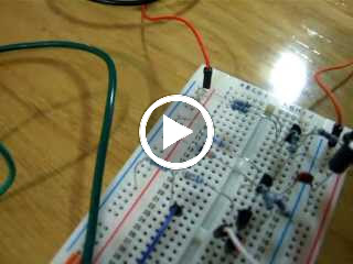
Step 1: Flashing LED with a PUT:
A PUT, Programmable Unijunction Transistor is similar in function to a normal transistor in the sense that it acts as a switch. When voltage is applied to the anode it either is blocked or allowed to flow depending on the value that the gate is set at. The voltage at the gate determines how high the voltage at the anode has to be for current to flow.
The first part of the circuit is setup to explain this theory. The 2 resistors at the gate determine the voltage at the gate (and thus the voltage barrier at the anode). A resistor at the anode protects the PUT from excess current. When the circuit is set up, the capacitor attached to the anode charges and thus the voltage increases until it reaches the voltage set by the gate and current flows through and lights the LED between the cathode and ground.

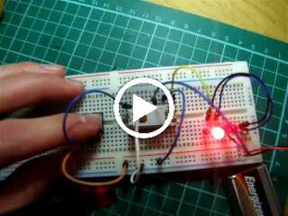
Step 2: Making a metronome with a speaker:
This is very much the same circuit as above however the LED is replaced with a speaker, there is a resistor in series with the speaker, I assume this is to protect the speaker or to stop it from distorting. The sound is only faintly audible because of the very low current. A metronome can be produced by using a capacitor with a larger capacitance, this slows the oscillating of the speaker, whereas using a lower capacitance results in a faster oscillation. In this circuit a 0.0047 uf capacitor is used, therefore the speaker oscillates fairly frequently.
This is very much the same circuit as above however the LED is replaced with a speaker, there is a resistor in series with the speaker, I assume this is to protect the speaker or to stop it from distorting. The sound is only faintly audible because of the very low current. A metronome can be produced by using a capacitor with a larger capacitance, this slows the oscillating of the speaker, whereas using a lower capacitance results in a faster oscillation. In this circuit a 0.0047 uf capacitor is used, therefore the speaker oscillates fairly frequently.
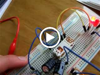
Step 3: Adding an amplifier:
In this step, a 2N222 transistor is added to amplify the current to the speaker so it makes a more audible tone. The collector of the transistor is protected by a resistor, the output of the PUT (cathode) is attached to the base of the transistor and then the speaker is put in series with the emitter and ground.
When the current flows through the PUT it reaches the base of the transistor which switches the current from the collector to the emitter. Because more current is flowing through the speaker it sounds louder.
Step 4: Adding another amplifier:
To give the speaker one final boost we add another 2N222, this time the speaker is hooked up between the positive voltage rail and anode, I assume it could also be placed in between the emitter and ground, the speaker only operates when the switch is open/the transistor is oscillating.
 |
| From MAKE Electronics: Videos |
Step 5: Adding step 1 (the slow oscillator) to the fast oscillator driving the speaker:
The output from the cathode of the PUT in the top circuit is joined to the gate of the PUT driving the speaker, I assume this varies the gate voltage which means that when the PUT in the top circuit is passing current, the the capacitor in the speaker PUT circuit takes less time to charge and therefore the speaker oscillates more quickly, thus producing a higher tone, then when the slow oscillating PUT is not passing current the capacitor charges slower (as it is having to reach a higher voltage) in the speaker circuit producing a lower tone in the speaker.